1. Context
1.1. About this tutorial
This tutorial is based on the official one from Argosim and available here: https://download.argosim.com/index.php/s/5ZszF09tl0rd4gv/download.
This tutorial will present:
-
methodology guidelines ;
-
how to create and use glossaries ;
-
how to write complex requirements ;
-
debug complex requirements ;
-
how to write scenarios to generate inputs ;
-
how to turn requirements into Observers.
All of that will be presented along a concrete system example: an automatic door controller.
2. Case study
2.1. Description
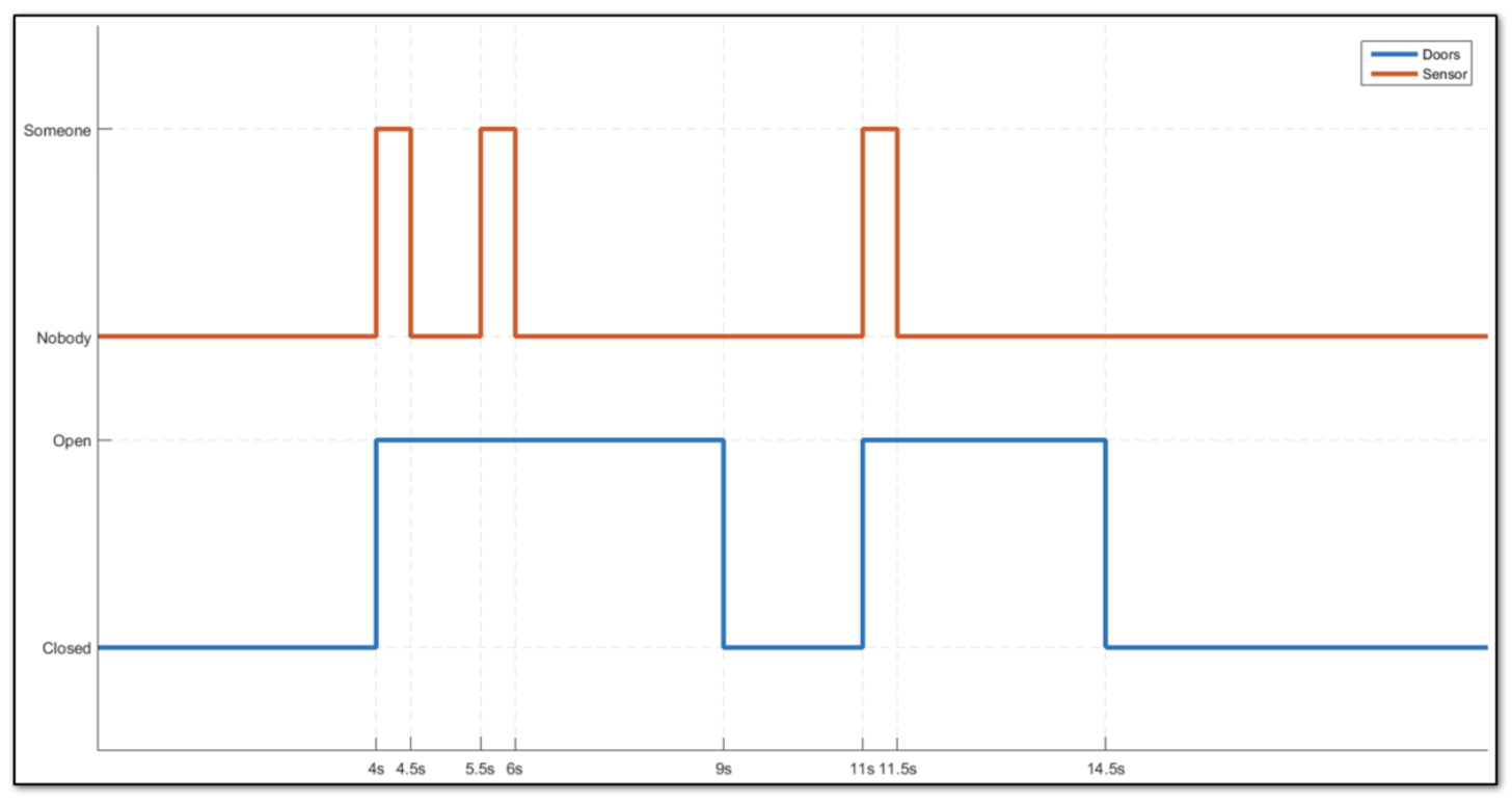
We will consider an automatic door system similar to the one at the entrance to your favourite mall. The informal specification is given by the picture in Figure 1. Depending on the value of some sensor, indicating if someone or nobody is detected, the door shall be open or closed.
2.2. Project structure
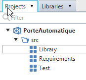
Create the following packages:
-
"Library" package is a place where you can add user defined templates to complement the Standard Library.
-
"Requirements" package is intended as a place to organise your system requirements.
-
"Test" package is somewhere to define scenarios and tests.
2.3. Create your first Glossary
A good practice is to start by creating a Glossary. It allows you to gather definitions of interfaces that can be shared among several systems. To create a new Glossary in the Requirements package:
-
Click to select the "Requirements" package.
-
Click on menu entry .
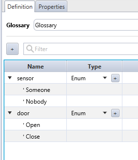
From the automatic door system description, we can identify two signals:
-
Sensor which can take the values Someone and Nobody.
-
Door which can take the values Open and Closed.
Add these two definitions to the glossary by clicking on the + button.
Choose Enum as type in the dropdown list.
Double click to edit the created EnumItem and type Someone.
Add the other enumerated value by clicking on the + button.
3. Requirements
3.1. Using the Glossary
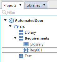
To create the first requirement of our automatic door system:
-
Click to select "Requirements" package
-
Click on menu entry .
-
Name it "Req001".
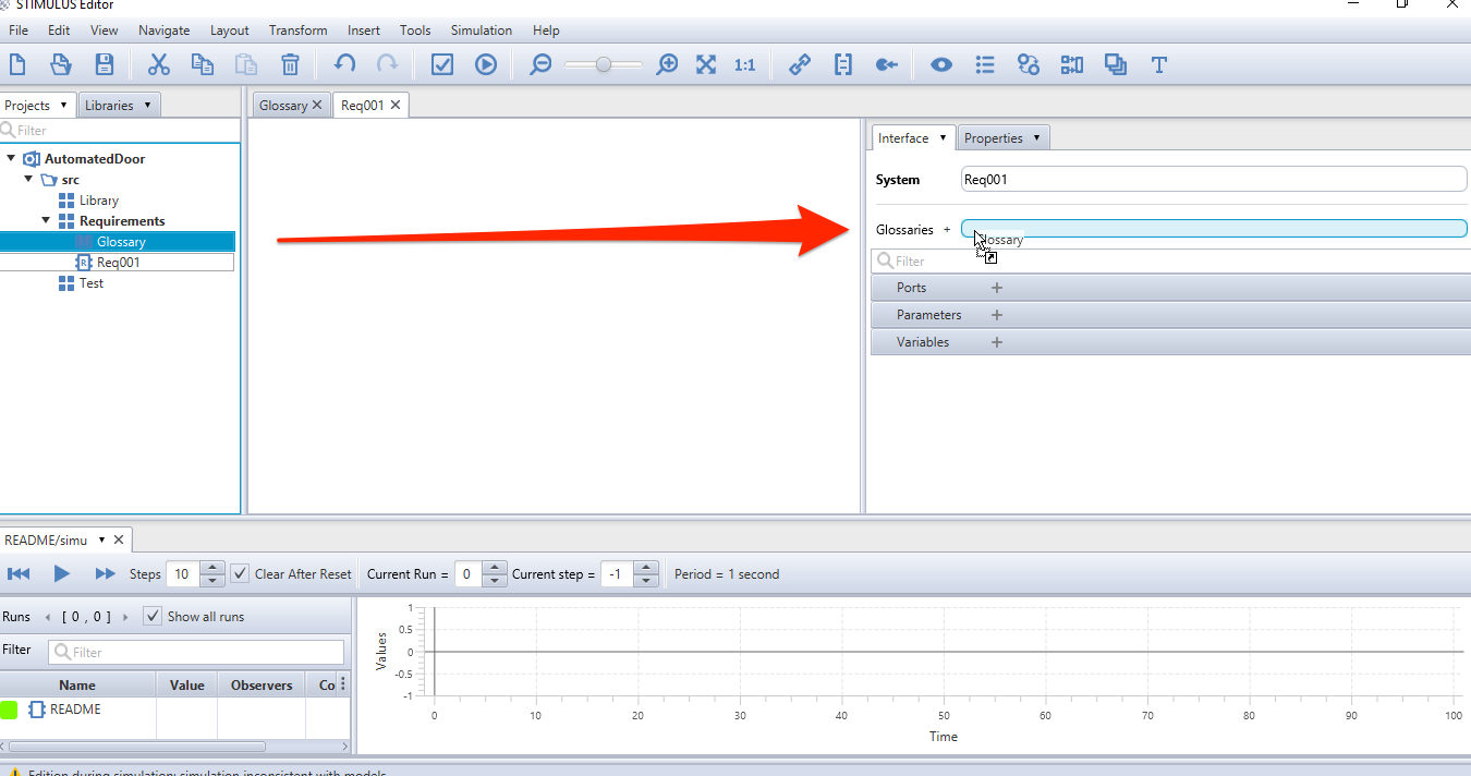
To use the glossary, drag and drop it from the project navigation tree to the system interface as in Figure 5.
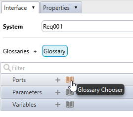
Glossary chooser buttons then appear in the interface with book icons, that will help you to declare ports from a glossary definition as shown in Figure 6.
3.2. Requirement definition
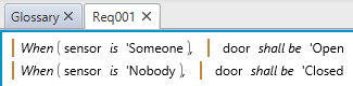
We first consider the two following basic requirements: "When there is somebody, door is open" and "When there is nobody, door is closed". Drag and drop from the Standard Library the necessary and items. Then complete to obtain Figure 7.
| The figure has been taken after some polishing in the format of the items… |
3.3. Simulation 1
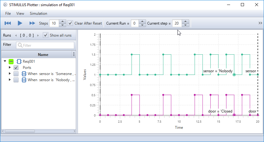
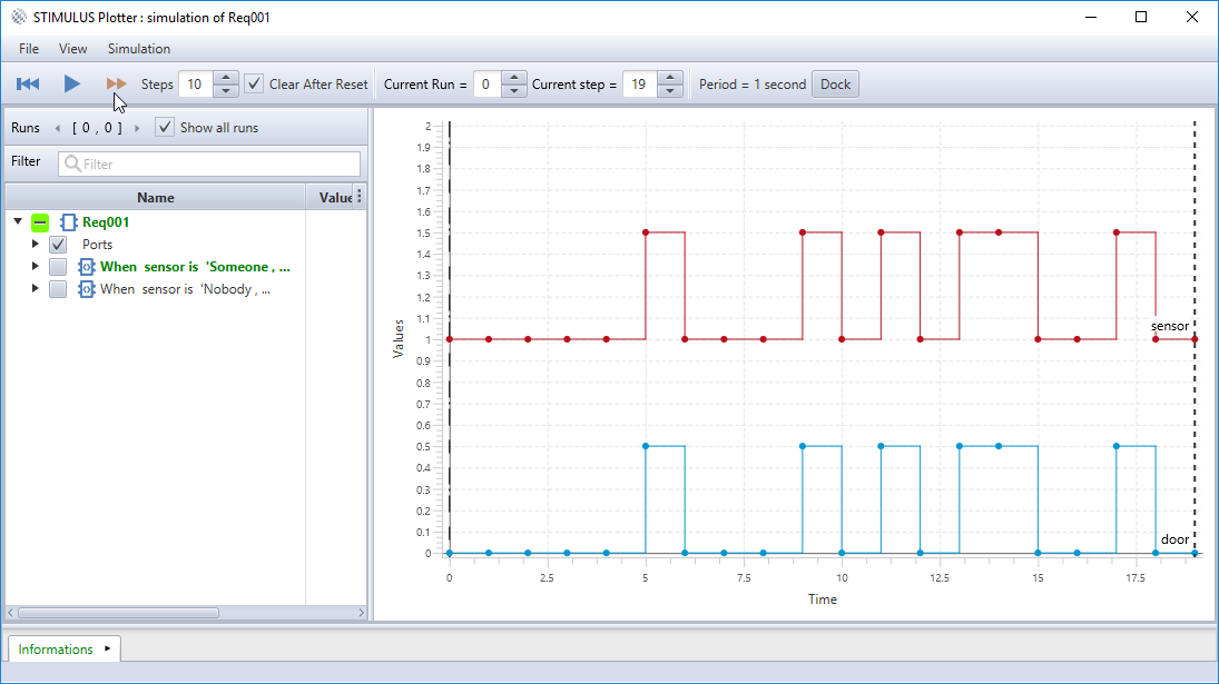
Now run a simulation and do some steps as in Figure 8.
We observe that the behaviour of the basic requirements does not reflect the delay, expected after the door has been 'Open.
|
3.4. Requirement improvement
Using the item and the drag & drop, add a 3 seconds delay as shown in Figure 9.

3.5. Simulation 2
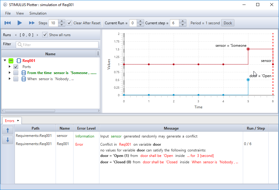
Now run a simulation and do some steps as in Figure 10.
We observe that the behaviour is not the expected one!
Surprisingly, the door is not kept open.
Why ?
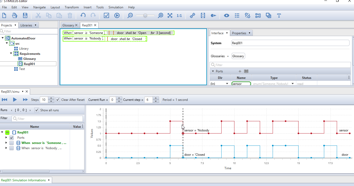
To understand, select in the plot window the step where the door changes from 'Open to 'Closed.
In the system window, we observe that the For 3 [second], Door shall be 'Open sentence is not active at this simulation step, as shown in Figure 11.
This is due to the When which deactivates its <BODY> when condition is false!
|
3.6. Requirement fixing
Actually, what we wanted to say is "From the time someone is detected, then we shall do something for 3 seconds".
Drag the item from the Standard Library and drop it over the first When in order to replace it, as in Figure 12.

3.7. Simulation 3
Now run a simulation and do some steps as in Figure 13.
3.8. Requirement fixing again
Of course, there is Nobody, we say that the door shall be Closed, and at the same time, we require the door be kept open the door opened for three seconds.
Therefore the second requirement is obsolete.
To remove it, select it and press Delete on your keyboard, then simulate again.
3.9. Simulation 4
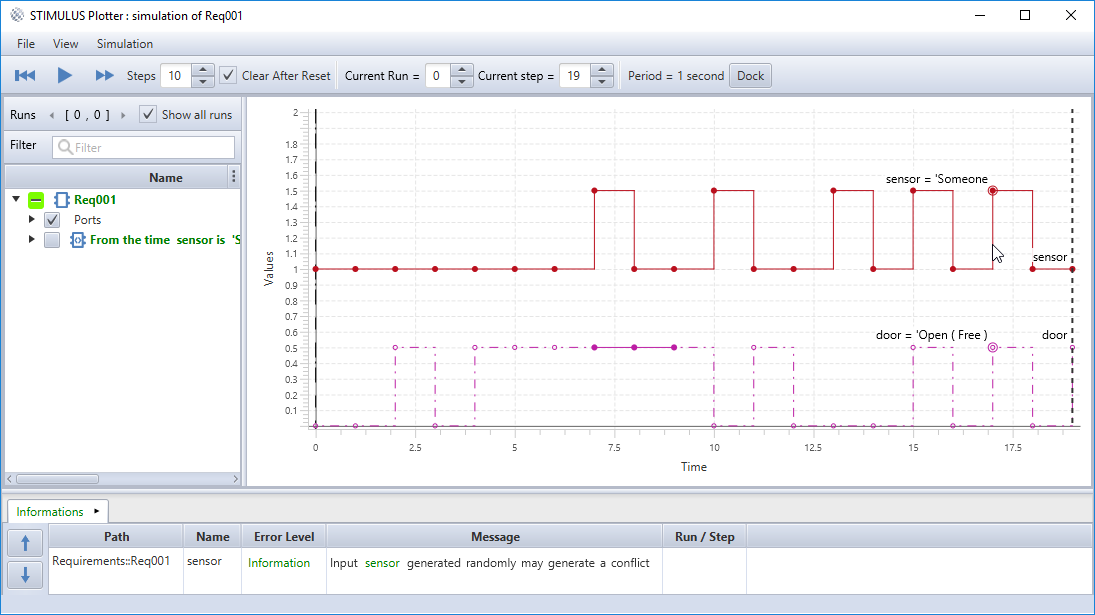
Now run a simulation and do some steps as in Figure 14…
3.10. Simulation 5
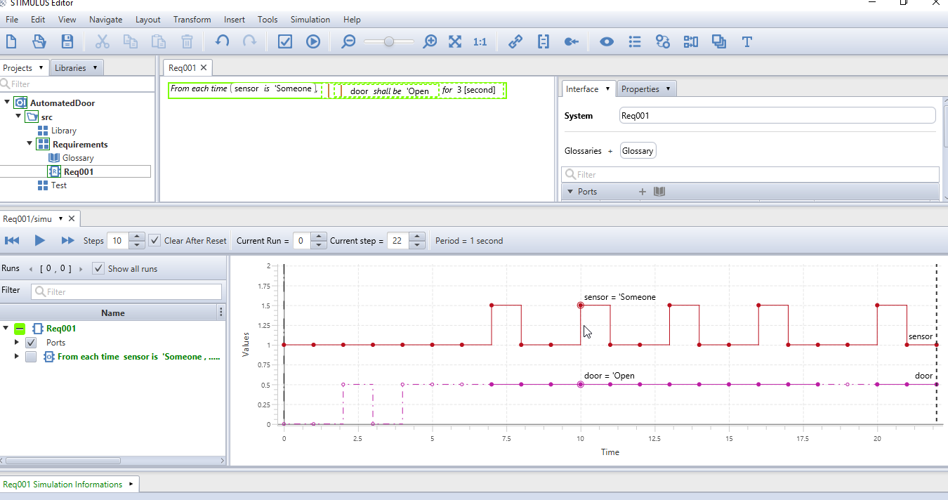
We observe that the door remains open for a number of seconds (more than 3) after someone has been detected.
However, the door remains closed when someone is next detected.
We also notice that the door line is dotted until the end of the simulation, which means that no requirement applies during this period of time and Stimulus is free to choose whatever value for Door, Open or Closed, that it wants.
Since the door behaviour is free, the door can be equally open or closed.
Doing some simulation steps, we see the door is always free, even if someone else is detected again. Actually, we want to repeat the "open for 3 seconds" behaviour each time someone is detected.
Drag the item and drop it onto the From.
Then, simulate again.
3.11. Simulation 6
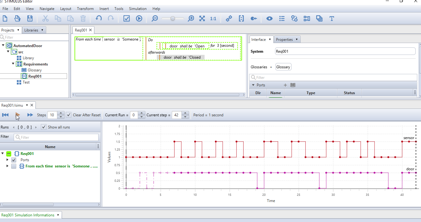
The door opens again when the second person is detected, which is fine. However, the door is still open a long time after the first person, and we really want to close the door three seconds after the latest detection. This sequence can be specified with the item. Use it to obtain the following requirement (see Figure 16 and the resulting simulation in Figure 17):

3.12. Simulation 7
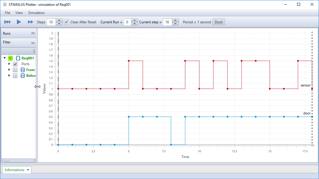
Some requirement is missing. We want the door to be closed before the first person is detected. Try to add the requirement to end up with the final simulation illustrated in Figure 18.
4. A scenario for the Sensor
As explained in previous section, the Sensor signal is toggling too fast.
We would like to test the door system by increasing our control over the input of the system.
To do so, we are going to create a scenario for Sensor.
Start by creating a System into the Test package, and call it SensorInput.
As for "Req001", import the glossary "Glossary" and declare the Sensor port with the glossary chooser.
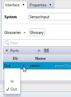
We recommend that you manually set the direction of scenarios ports.
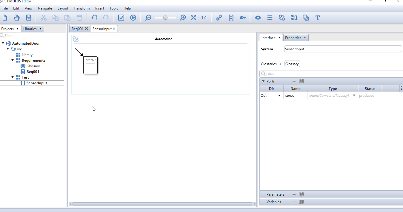
In this case, set Sensor direction to Out, as shown in Figure 19, in order to make sure that only this scenario will produce the Sensor value.
To write the scenario, we will use a new Stimulus concept: the Automaton, also know as a state machine. Of course the Automaton concept can also be used to write requirements. Actually Stimulus makes no difference between "requirements" and "scenarios". For it, they are only Systems. Calling a System a "requirement" or a "scenario" is from the user point of view. To insert an Automaton, drag and drop one from the toolbar in your system window. A new automaton appears with an initial state ("State0") in the system window as shown in Figure 20.
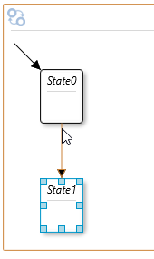
To create another state, place your mouse cursor near the state bottom border, a little orange triangle appears as in Figure 21, double click on it. A new state "State1" appears, connected to the first one by a transition.
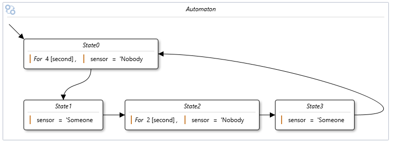
Then, complete the automaton as in as in Figure 22.
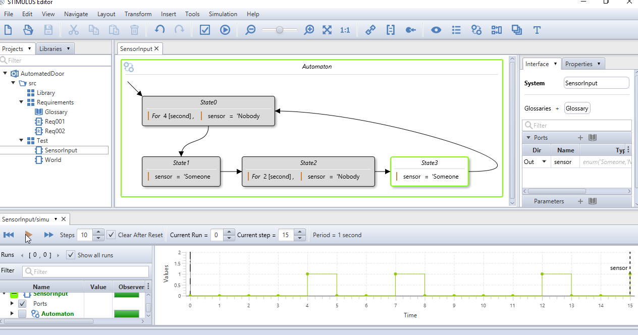
Observe generated values as shown in Figure 23.
5. Testing door system
To test the door system, we will create a top-level system, using a block diagram, to connect the door system and the scenario we just created as input. First, create a system named "World" in the Test package.
Then we will use a block diagram to graphically connect systems. Drag and drop a new block diagram from the main toolbar into the "World" system.
To insert a block referencing the "Req001" requirement, drag and drop it into the block diagram area. A box appears, it represents our "Req001" requirements and its interface.
Do the same for the "SensorInput" system. To link Sensor from "SensorInput" to "Req001" one, drag from the output port and drop onto the input one.
In order to visualise block diagram inner signals, we need to place probes over the links. Click to select "Req001" box, then click on menu entry to obtain Figure 24.
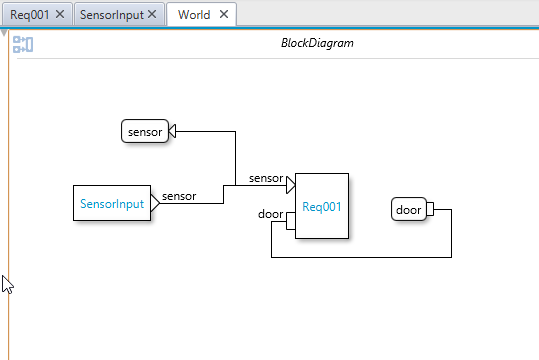
Simulate as in Figure 25. The door is closing and opening as expected. We recommend that you create other scenarios to complete door system test.
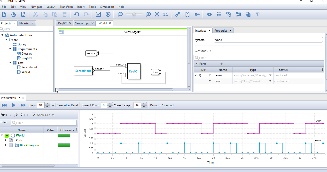
6. Requirements Observers
To enforce requirement quality, we recommend that you check safety requirements violations through your requirement writing process. Stimulus allows you to transform requirements into Observers that will check your current requirements behaviour. You can also check for violations on any refined or rewritten requirements. In the door system, as a safety requirement, we would like to guarentee that when someone is detected, the door shall not be closed.
To create an Observer, drag and drop an Observer from the main toolbar (see Figure 26).
To rename the observer, double click on the title, and name it "Safety". Then, we can write the safety requirement we want to check during simulation, in the "Safety" observer.
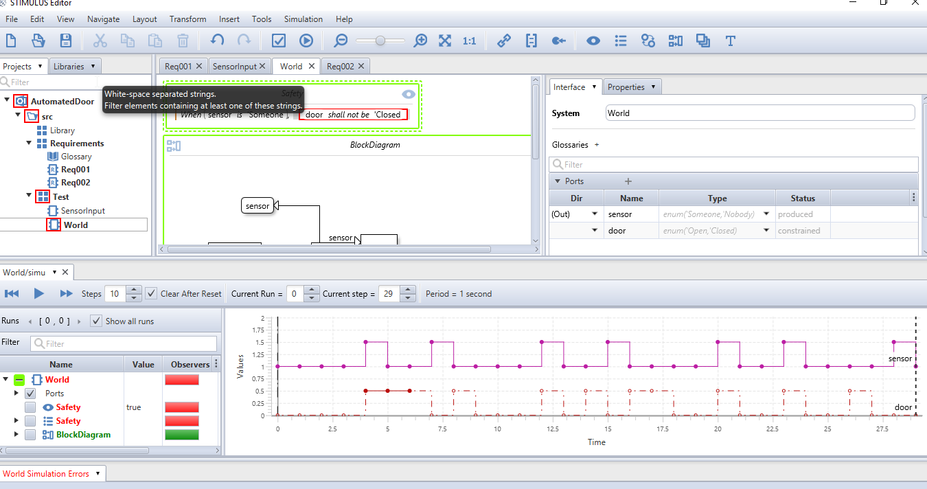
Any requirement declared inside an Observer will not constrain the system behaviour. Any violation will be reported in the plotter navigation tree. Simulate some steps and look at the status of the Observer, as shown in Figure 26
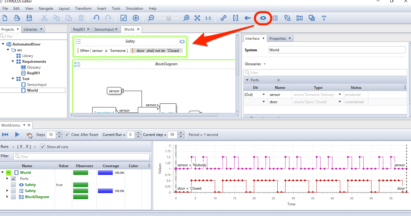
A green color means that no violation has been detected so far, as shown in Figure 27.
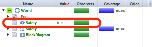
This Observer will ease your requirement writing process and your simulation analysis when running different scenarios. To illustrate what is an Observer violation, we will analyse a previous version of our requirements (the fourth one for example).
We simulate the "World" and we observe that the eye turns to red, it means that the Observer is violated, as shown in Figure 28. To get the explanation and the step where the violation occurs, click on the "Violated Observer" message in the bottom part of the window. The suspicious step is selected and we observe that the door is closed at the same time someone is detected, therefore violating our safety requirement.
7. Basic notions
7.1. Predefined, customizable templates
7.2. Composition
7.3. Refinement of requirement
7.4. Observers
High level requirements can be transformed as observers.
8. Advanced notions
Work in progress…
8.1. Glossaries
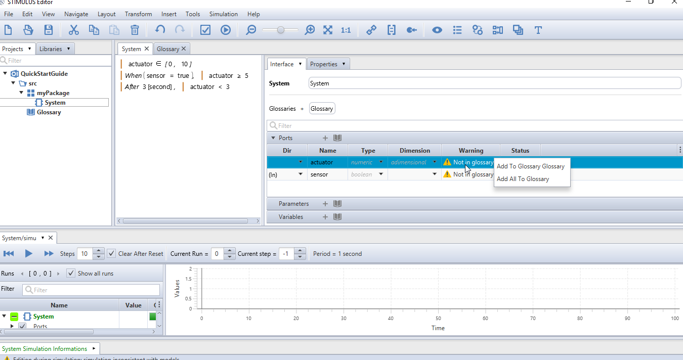
You can host the main definitions in a Glossary.
To start one, click on
You can add the Glossary to the Interface (by dragging the glossary close to the little + close to Glossaries) and then add the ports to your glossary by a clicking on them (see Figure 29).
| It can be a good idea to start with the glossary |
9. FAQ
9.1. Where can I find more material ?
9.2. What are the different simulation parameters ?

-
The simulate one step button performs one simulation step in the plot window.
-
The fast forward button performs N simulation steps. The number of steps is defined by the field at the right of the button.
-
The reset button starts a new simulation. When the Clear on reset checkbox is unchecked, the next simulation will be overlaid on the previous one.
-
The Period label displays the simulation sampling period. You can change this setting before a simulation in the Properties panel of your system. Insert a simulation period using a dimension (e.g., 1 [second] or 10 [millisecond]).
9.3. How can I find a function or language construct ?
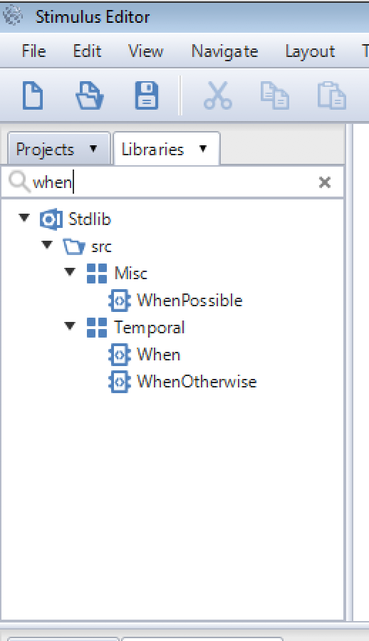
Select the Library folder and use the seach bar.
Figure 31 illustrates the search for the when operator.
9.4. How can I move a port on a system ?
To move a port in a block diagram, maintain MAJ (Shift) while moving the port with the mouse (left click).